Support
FAQ - Float Guided Switch (FGS)
It is a single/ multipoint float switch based on for Archimedes principle (float) and magnetism
1.For which applications/ services, float guided switch is recommended?
It is suitable for free flowing clear, clean, corrosive and non-corrosive liquids. Suitable for small
/medium sized tanks.
2.Whether the switch is used for slurry/sludge applications?
No.
3.In which material float guided switch is available?
It is available in SS304, SS316, SS316L, PP, PVDF and ECTFE ctd. SS316 material to suit corrosive and non-corrosive services.
4.Whether the switch is used for turbulent liquid?
Yes. By using perforated Stillwell with switch.
5.Whether switch can be used for interface level measurement?
Float switch with specially designed float of 60 mm diameter is suitable for interface level measurement.
Note - Difference between specific gravity of two liquids is > 0.2.
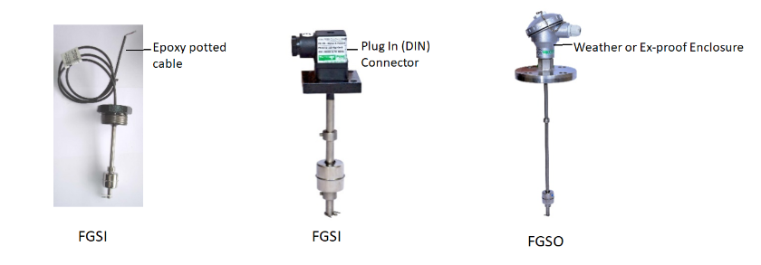
6.What is a difference between FGSO and FGSI?
FGSO – Float switch for outdoor installation is provided with weather proof or ex-proof terminal enclosure to protect its terminals.
FGSI- Float switch for Indoor installation is provided with either plug in (DIN) type connector or epoxy potted cable.
7.How many set points are available in single switch?
From one to maximum four
8.Whether the set points are adjustable on site?
No.
Preset levels are factory set. Preset points/ levels has to be informed by the user prior to
manufacturing.
9.Whether switch is used for hazardous area applications?
Yes.
Float switches with flameproof enclosure Ex d Gr. IIC T6 or ATEX Ex d Gr. IIC T6 or Intrinsic safety
switch with zener barrier are available for hazardous area applications
10.Whether CCOE/ PESO certified enclosures are available?
Yes. CCOE/ PESO certified flameproof enclosures are available for hazardous area applications.
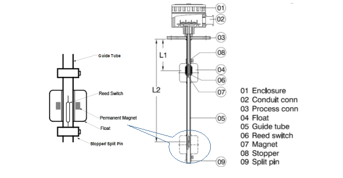
11.What type of sensor is used in float guided switch and how does it work?
Reed sensor is used as switching element. It actuates (change over the contact) when it comes in vicinity of magnetic flux of a float.
12.Whether the float switch requires power supply
No.
13.Whether the reed sensor is hermetically sealed? What does it mean?
Yes.
Reed contacts are sealed in the glass tube by filling inert gas in it to protect the reed contacts from
corrosion due to atmosphere.
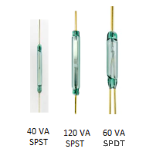
14.What type of reed sensors are available?
Reed switches are available as
1) 40 VA or 120 VA (NO or SPST contact form)
2) 60 VA (SPDT contact form)
Note: VA is power rating of the reed switch
15.How to select reed sensor type for particular application?
Selection is based on
1. Load (mA) to be connected to switch – Refer reed switch contact details in catalog
2. Switch contact form (SPST or SPDT
16.Whether the switching O/P can be connected to PLC/DCS or BMS system?
Yes
17.What is understood by “VA rating” of a reed sensor?
‘VA’ stands for ‘Volts x Amperes’.
‘VA rating’ of a reed switch indicates its maximum power handling capacity. While connecting the load, the product of ‘Volts x Amperes’ should not exceed the VA rating of the switch.
18.Whether 230 VAC can be used for switching supply?
Yes. Provided its power rating (40VA/ 60 VA/ 120 VA) and maximum switching voltage & current rating of particular reed sensor is fulfilled.
It is recommended to use the switching voltage of 24 VDC for its better operation
19.How to use switch for higher load application?
Power rating of the reed switch is low.
To operate higher load, output switching contacts of the float switch is used through relay logic or use with Techtrol Level Controller (TLC-F) having its relay contact rated for 5A @ 250 VAC
20.What is the life of reed switch?
A reed switch can withstand one million operations when used within the limits of its
specifications.
21.What type of floats are available?
Float diameters according its material are listed as under
SS316 : ø 25,28,40,42, 60 or 75 mm
PP : ø 25, 50 mm
PVDF or ECTFE ctd SS: ø 63
23.How to select float size?
Select Float size to suit
- ID of nozzle on the tank (Ensure float get easily passed through the nozzle)
- Specific gravity of the liquid
- Process connection and number of set points
- Operating temperature and pressure
Note: Refer float selection table in catalog.
24.How does float guided switch work?
Reed switches are placed at various locations (set point) inside the guide tube. Reed switch contacts are taken out and connected to terminals fitted inside the enclosure. Float fitted with magnetic system, moves freely on guide tube according to liquid level. Reed switch gets actuated when it comes in magnetic field of the float.
25.How does float guided switch works with single float and multiple float?
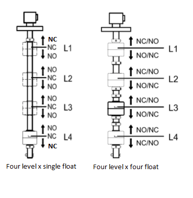
Switch actuation using single float
The switch is provided with two stoppers,
one above the highest set point (L1) and other below the lowest set point (L4).
With single float, switching actuation is bi-stable at highest and lowest (L1 & L4) level.
In between (i.e. at L2 & L3), it is mono-stable. Refer adjacent figure.
Switch actuation using multiple float
By using separate float for each set point,
switch actuation is bi-stable i.e. switch
actuation (NO or NC) is hold/ latched
during rising or falling of liquid level, as the
movement of the float is restricted by the
stopper at each set point.
26.What information is required to get quotation earliest?
1. Tank Details : Tank MOC & Height,
: Nozzle ID & its length
2. Mounting Position : Top/Bottom/Side
3. Process Connection : Flanged or screwed or triclover ferrule
4. Process Details : Liquid and its Sp. Gr Specify viscosity, suspended particles & turbulence if any
5. No. of set points : one /two/three or four
6. Optg. Conditions : Operating temperature & pressure.
7. Other : Switching contact (NO or NC) at preset level during float (liquid) rising or float falling.
: External chamber (if required) and its CC distance
27.What is maximum guide tube length of the switch?
1 mtr for FGS with float dia 25 & 28 mm
3 mtr for FGS with float dia >/= 40 mm
28.When Stillwell or External Chamber is used?
Stillwell is employed if liquid is turbulent and sufficient space is available in the tank.
External chamber is employed in case -
1. There is limited space within the tank
2. Mechanical stirrers cause turbulence in liquid
3. Tank needs to be isolated frequently for regular cleaning/servicing.
29.How does latching function works in Techtrol Level Controller?
Latching function can be set through DIP switch provided in the controller. Let’s illustrate it with below
example of pump in application.
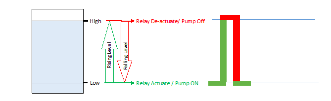
Filling Operation - Once the low level is sensed, relay against it gets actuated (pump-on) and remains
actuated on further rise of liquid. Relay de-actuates (pump-off), when high level is sensed.
Draining Operation – Relay status at high level remains de-actuated on further fall of liquid level.
Relay actuates (pump on) again at low level.
Thus pump-in operation is controlled between two set points of level switch or vice a versa for
pump –out operation using Techtrol Level Controller.
30.Why liquid specific gravity /density is important for float switch?
Float must follow the liquid level by floating on liquid. If sp.gr of process liquid is lower than the
rated sp. gr of float, the float will sink in the process liquid and switch will not work.
31.What is meant by intrinsic safe float switch
Intrinsically safe float switch is provided with Zener Barrier through which the power of switching signal (voltage of 24VDC and current 110mA) is limited so as to prevent ignition in hazardous area
32.What precaution should be taken while using the switch for longer life?
Please ensure -
1. Switch material is suitable for process liquid.
2. Process Liquid should be free flowing and should not contain heavy suspended particles or should not get scaled on float which may restrict the float movement.
3. Liquid should be free from suspended magnetic particles which may stick to float magnet and restrict its movement.
4. Float selection is suitable with specific gravity of liquid
5. Max operating temperature & pressure is always within its specified limits
6. The load connected to switch should be less than its VA rating, else use relay logic or Techtrol
controller TLCF for higher load
33.What approvals & certifications are available for the switch?
Approvals/ Certification
- CE as per low voltage directive
- CCOE /PESO (Enclosures)
- ATEX Ex d as per 2014/68/EU
- Marine (IRS)
Testing & Documentation
- Hydro testing
- PMI
- Material Certificate as per 3.1 (EN10204)
- Radiography
- Other testing available on request
34.Advantages of float guided switch
- Reliable and accurate level detection
- Single as well as multiple set points
- Set points are factory set, ready to install on tank top.
- Do not require electricity. Reed switch operates due to magnetic flux of the float
- Easy to install with screwed or flanged connection
- Potential free output can be directly connected to PLC/DCS or BMS system
- Customized guide tube length to suit tank height.
- Flame proof enclosure or intrinsic safety switch for hazardous area applications
- Miniature version with single set point is available for small tanks.
All Rights Reserved © 2021 PUNE TECHTROL PRIVATE LIMITED
Engineered by THE IMPALS