Support
FAQ - Reflex Level Gauge (RFG)
1.For which applications/ services RFG is used?
It is used for safe visual indication of clean liquids under high temperature & pressure where tubular level gauges are not suitable - water, acids, alkalis, dosing chemicals, brine, solvents, alcohol, ammonia, therminol, hydrocarbon, diesel, oils (fuel, lube).
2.Whether RFG is used for viscous liquids?
It can be used for free flowing viscous liquids.
3.What wetted part materials are available in RFG?
CS, CS ASTM A105, SS304/316/316L, PP or rubber lined CS.
4.What type of glass is used in RFG?
It is a tempered/ toughened borosilicate reflex glass.
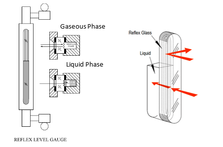
5.How reflex gauge works? how level is observed?
It works on principle of refraction of light through vapor and water due to its refractive indices. The reflex glass has prismatic 45 ° grooves on its one side, which is placed on liquid chamber facing the liquid / steam. The light falls on gauge glass portion covered with liquid, gets refracted/absorbed in the liquid showing black color to viewer, whereas the light falls on the portion covered with vapor/air gets reflected towards viewer to appear as silvery white.
6.What is the CC distance range available in RFG?
200 to 2200 mm
7.Whether RFG can be used for large tanks?
Yes.
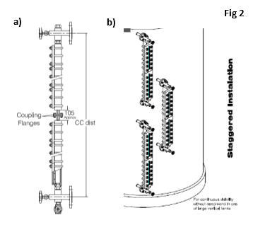
For large tanks, multiple RFGs are installed on tank in staggered arrangement.
However, dual RFGs with flanged coupler arrangement can be provided upto 3000 mm. Necessary support should be provided for the same at site.
8.What is difference between coupler and staggered arrangement?
- Coupler arrangement
1. Two gauges are connected to each other with coupler flange arrangement.
2. Only two process connections are required to mount level gauge.
3. The liquid level cannot be observed at the location where the gauges are connected. (200 mm aprox.) 4. Necessary support for the gauge should be provided at site.
- Staggered Arrangement
1. Two or more gauges are installed on the tank with overlapping
2. Process connections will be more than two.
3. No. of process connections = 2 x no of gauges 4. Provides continuous visibility
9.What is the difference between straight- through and hook-up type of RFG?
Straight through RFG (Top-Bottom Connection) - In this construction,
end blocks are connected at and bottom of the liquid chamber and hence
visibility of the gauge is lesser than the CC distance.
Hook - up RFG (Side-Side Connection) - Here end blocks are connected
to side of the chamber and visibility of the gauge is same as CC distance.
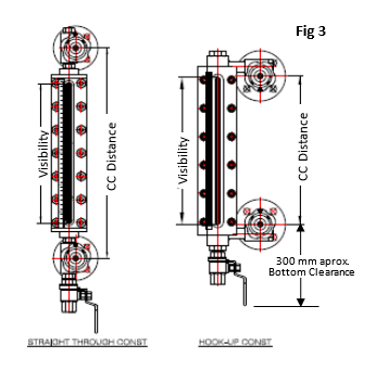
10.10. How much bottom clearance from lower nozzle to ground is required to install RFG on tank?
Bottom clearance required is approximate 300 mm in case valve is required at drain. Refer fig 3,
11.For what temperature range RFG is suitable?
RFG in metallic construction is suitable for temperature -40 to 400 °C and RFG in PP material -10 to 70°C
12.For what maximum pressure does RFG works?
It is available in four pressure ranges as under
Low pressure – vacuum to 30 kg/cm2
Medium pressure – vacuum to 85 kg/cm2
High pressure – vacuum to 165 kg/cm2
Very high pressure – vacuum to 210 kg/cm2
Note: RFG in PP MOC works upto max. pressure of 2 kg/cm2
13.What is least count of the scale?
Calibrated scale is available in Polycarbonate with LC of 2 mm and SS304 MOC with LC of 5 mm or 0.5 cm
14.What safety feature is available in RFG? How does it work?
Auto ball check (ABC) facility is provided as safety feature to prevent liquid loss in the event of glass break.
It consists of capsule and freely moving ball along its inner race between stopper and orifice. It is placed in the nipple of end block at bottom and top side. In case gauge glass breaks, high pressure from vessel side (atm + liquid column) moves the ball to block the orifice and minimize liquid loss from tank.
15.What is the use of integral offset gauge valve?
Integral offset gauge valve – It is an integral part of end block used in gauge at top and bottom. It is off center to inlet of gauge to regulate liquid flow coming inside the liquid chamber. By opening needle valve, liquid in the tank can be observed through glass. During maintenance, cleaning of glass or its replacement can be done by closing the offset valve.
16.When frost free extension is recommended with RFG?
It is recommended for clear visual reading of low temp liquids. It is used to prevent frost formation on gauge glass.
17.When Illuminator is recommended in RFG?
It is recommended for installation of gauge in poorly lit area. Illuminator provides uniform light along the glass length for clear visual indication.
It consists of Perspex reflector, illuminated through a LED bulb, 80 to 250 VAC with Al. Enclosure IP65 /Ex d Gr. IIB or IIC. The length of single illuminator is 1200 mm max.
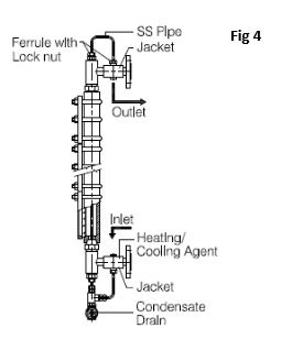
18.When Jacketing is recommended in RFG?
It is recommended for liquids, which gets solidified at amb temp. It prevents solidifcation of liquids at amb. temperature. It consists of a SS pipe, which pass through liquid chamber with inlet & outlet of ½” NPT (F) at bottom and top end block of gauge. Heating (steam) / cooling agent is passed through this pipe to maintain service material in liquid state.
19.What is standard process connection orientation in RFG?
Standard process connection orientation is rear – rear. However, it is available in left-left, right-right orientation as required.
20.Whether RFG is used for steam applications?
Yes. IBR approved gauge is available.
21.What is maximum temperature & pressure of IBR RFG?
Max. temperature – 243 °C and max. optg. pressure – 32 kg/cm2
22.Whether RFG is used for interface liquids?
No. Liquid interface cannot be observed separately through the reflex glass.
23.What are advantages of RFG?
- Robust & safe design for high temp & pressure applications
- Direct visual indication of liquid
- Distinct and clear liquid level indication in black color is visible from distance.
- No need of power supply
- Easy to install through flanged or screwed connection
- Available in PP to suit corrosive application
- With integral offset needle valve, performing maintenance tasks or cleaning the glass becomes a much simpler process.
24.What information is required to get quotation at earliest?
Tank size, CC distance, process connection, liquid, operating temp & pressure.
25.How RFG is installed on tank?
It is screwed/ bolted to process connection provided on side wall of the tank.
Ensure mounting is in plumb.
Use appropriate gasket between the process connection to prevent leakage.
26.What approvals & certifications are available for RFG?
- CE
- IBR
- IRS (Marine)
- Material certificate 3.1
- NACE
All Rights Reserved © 2021 PUNE TECHTROL PRIVATE LIMITED
Engineered by THE IMPALS